Category: TECHNICAL INFORMATION BULLETIN
Back to gazoogene
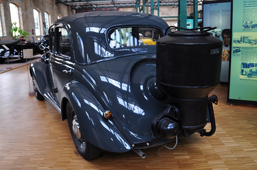
Like most gasifier vehicles the range of Mercedes gasified cars appeared during the Second World War. Mercedes appears in history around 1926 under Daimler-Benz, but origins seem to go back to the Daimler-Motoren-Gesellschaft’s 1901 Mercedes and Karl Benz’s 1886 Benz Patent-Motorwagen. Mercedes-Benz’s slogan is “Das Beste oder nichts” (English: “The best or nothing”). So one would imagine thate Mercedes gasified cars were no different.
Fast moving parts catalog 2016
2015-2016 One Safe Source Link
Welcome to the newest edition of the One Safe Source catalog. Inside you’ll find part numbers, descriptions, sizes and more for thousands of genuine Cat® parts — all manufactured to strict, original equipment specifications. You can count on these reliable, durable Cat parts to deliver top performance and long life in your applications — and you can count on us to provide the right parts and service solutions, when and where you need them.
We carry most of the parts featured in this catalog for your immediate, off-the-shelf convenience. And thanks to Caterpillar’s worldwide distribution system, we can deliver most others within 24 hours. If you can’t fi nd what you’re looking for, just ask. Plus, our highly trained experts understand the complete lineup of Cat parts — original, Classic and Reman — and can answer any questions or make recommendations.
This catalog contains only high-volume parts. If you are looking for something different, we may have what you need in stock or can order it for you quickly. Whether you’re maintaining one Cat machine or many, you can turn to us for the parts, comprehensive service options and total support that keeps you up and running — maximizing your equipment investment.
Part numbers and specifi cations are subject to change without notice. To ensure you receive the correct parts, please provide the model and serial numbers of the machines or engines on which they will be used. Some of the products listed in this catalog are not available in certain parts of the world. Please check with us for more information.
Cat power generation module
Caterpillar launched the Cat offshore power generation module, a turnkey scalable, single lift, modular power plant product. The unit offers full integration into a floating, production, storage, and offloading (FPSO) vessel or a fixed production platform’s structural design. It was
designed specifically to meet the needs of FPSO and fixed production platform’s main power applications in cases where a gas turbine was not ideal. Available from 4 MW to 17.3 MW per module, the unit runs on liquid, diesel, crude, and heavy fuel oil or gas. It also runs in dual fuel mode and meets current and future emission regulations to maximize flexibility and reduce operating costs. The modular layout can be expanded to provide power for future upgrades. The
integrated design is complemented with flexible manufacturing and the power module is equipped with remote monitoring.
For more information, visit www.caterpillar.com
Acert technology
| Acert by Cat |
Andrew Norton headed to the US for a firsthand look at Caterpillar’s acert technology
Cat out of the bag
Caterpillar is the world’s largest manufacturer of diesel engines, with more than 500,000 units sold each year. Established in 1925, it currently employs more than 80,000 people directly, with a worldwide dealer network of 182. The annual sales are almost AU$36.5 billion.
The marine division, known as Caterpillar Marine Power Systems, is headquartered in Hamburg, Germany, where medium-speed heavy fuel oil MaK Motoren diesels (the company was acquired in 1997) are built. Caterpillar also owns the Perkins factory in Peterborough, UK, which manufactures smaller diesels and gensets using a mix of CAT and Perkins technology.
But Peoria, Illinois in the US is Caterpillar’s headquarters for highway, construction/earthmoving, commercial and pleasureboat diesels that operate on distillate, and this is where the C-Series of marine diesels are concepted, designed, and evaluated. The research and development facility is at Mossville and the straight-six C10 to C18 engines are cast at Mapleton, both a short drive from Peoria.
TOUR OF DUTY
Shortly after the release of CAT’s ACERT low-emission, diesel engine technology at the 2006 Sanctuary Cove Boat Show, Phil Canning from Energy Power Systems, the Australian distributor of CAT marine engines, discussed with me the benefits of the ACERT components. After a lengthy phone conversation, Phil decided the best way for me to gain a thorough understanding of how ACERT functions was to get me to the Mossville head office to tour all of the company’s engine manufacturing facilities.
As part of the negotiations for me to tour the office, there had to be an agreement that the engines I saw being evaluated at the Mossville R&D facility would not be discussed in print until they were officially released. In early July, I flew with Garry Dann, Energy Power’s Queensland sales manager, to Peoria to tour the facilities.
After an exhaustive two days of touring the Mapleton foundry and the Mossville head office I was able to appreciate the attention to detail in the R&D facility, the foundry, and the engine assembly lines, and the way in which CAT operates its business.
For example, CAT only builds engines against firm orders. This minimises stockpiling and improves profitability because the majority of diesels ordered are customised according to the customer’s requirements.
At the Mossville Technical Centre, engines are concepted, designed and evaluated through several trial stages. Trial engines are tested for maximum power and torque outputs using dynamometers to simulate varying load conditions while meeting ever-stringent US and EU exhaust emission requirements.
They are tested for reliability in all ambient temperatures, from desert conditions (CAT supplies engines to Haliburton for Iraq) to Arctic and Antarctic climates.
Engines undergo thousands of hours of evaluation before being released on the world markets, and some units I saw being evaluated won’t be released until 2008.
Located alongside the Illinois River, the Mapleton foundry casts blocks and cylinder heads using separate moulds for each engine. The sand for the moulds comes from the banks of the Illinois River while the resin used (the ingredients remain a secret) comes from a company specialising in casting moulds. Upper and lower moulds are used for both the cylinder blocks and heads and are baked to 300 degrees, with a final microwave heat to ensure consistent grain throughout the moulds. When touched, these have a slightly sandy feel.
The foundry has a viewing gallery over the ladles and pouring lines for the grey iron, so we were able to see firsthand the process of pouring into the moulds, similar to the ‘lost foam’ technique used by some outboard engine manufacturers. The sand/resin mix vaporizes, leaving a fine grain cast iron. The residual black sand is used for landfill.
When the castings have cooled they are picked up and shaken from the steaming sand/resin slag, then cooled for a day and, if needed, sanded, ready for shipment to the Mossville assembly plant. CAT’s reputation for high quality casting is well known in the engine industry and the company casts blocks and heads for V8 petrol racing engines used on the Nascar circuit.
Back at Mossville, CAT utilises assembly teams whereby a handful of workers assemble one engine at a time. The working conditions were very good and the cleanest of any engine manufacturer I’ve toured. From an engineering viewpoint the way the engines were assembled, such as using special tools to insert pistons in the cylinders, was a real eye-opener compared to other production techniques I’ve seen. The forged pistons don’t have traditional skirt designs, reducing weight and stresses on the conrods and crankshaft.
Forged by a specialist supplier, the crankshafts are heated to 800 degrees, then cold-water quenched for two minutes to improve hardness and longevity. Once assembled, each engine is subjected to a ‘cold test’ in which, without firing it up, the engine is run to 600rpm to check for harmonic balance and oil pressure.
ACERT
Originally developed for on-highway diesels to meet tough new exhaust emission regulations, CAT ACERT encompasses four main areas of technology. The first is fuel delivery. CAT uses ‘microburst’ technology whereby fuel is injected in up to five short bursts before top dead centre (TDC), with the main spray occurring at TDC. The fuel is injected using either hydraulic electronic unit injectors (for larger engines) or electronically-controlled mechanically-actuated unit injectors) at pressures of up to 22,400 to 23,800psi.
The next area of technology employed by ACERT is CAT’s ADEM electronic engine management system, which optimises the air/fuel ratios and spray timing according to barometric pressure and engine load.
The third is air management, including variable valve timing on the intake valves and/or series turbocharging using a combination of high and low pressure turbochargers to avoid the need for either variable geometry turbocharger vanes or a mix of supercharging and turbocharging, both of which CAT deems as unnecessarily complex.
The fourth is a combustion chamber designed to maximise air/fuel burn efficiency to help produce power and torque while remaining within emission requirements.
Fortunately all CAT ACERT marine engines meet US EPA Tier 2 requirements scheduled for implementation in 2007, without needing variable valve timing or series turbocharging.
Engines with ACERT technology in the Caterpillar recreational marine diesel range include: the C7, which develops 455hp at 2800rpm;
the C9, which develops 567hp at 2500rpm;
the C12, which develops 705hp at 2300rpm;
the C15, which develops up to 853hp at the same revs;
and the C32, which develops a whopping 1800hp, also at 2300rpm.
In comparison, the existing C32 develops 1651hp at the same revs.
For more details on the CAT ACERT range, contact
Garry Dann
at Energy Power Systems
on (07) 3722 1400,
or email Garry.Dann@energypower.com.au
C8.7 High Performance Propulsion Engine by FPT Italy
The C8.7’s sophisticated fuel delivery system allows the use of a radial, belt-driven supercharger in addition to the conventional turbocharger; this feature eliminates smoke and reduces lugging, while delivering phenomenal low-end torque and impressive fuel economy. .
FPT ( Fiat Powertrain Technologies) Industrial’s advancements in second-generation common rail fuel injection systems paired with an innovative air management system allows the compact C8.7 to develop an impressive 650 mhp @ 2300 rpm while meeting EPA Tier 3, IMO II, and CCNR Stage II emissions requirements.
Caterpillar Incorporated and FPT Industrial S.p.A. announce an agreement in the field of marine pleasure craft engines. According to the new agreement, combining the vast marine know-how of Caterpillar and the leading edge technology of FPT Industrial, the new Cat C8.7 and Cat C12.9, with a displacement of 8.7 and 12.9 liters respectively, will offer yacht manufacturers a broad array of horsepower ratings ranging from 650 to 1000 mhp. In order to meet customers’ unique requirements, each engine will be offered in several different configurations; all will conform to Tier 3 emissions regulations.
Caterpillar has been a mainstay in marine propulsion for over seventy years, while FPT Industrial is a firm that can trace its roots back to the turn of the twentieth century. The new venture between the two revered engine manufacturers will provide unmatched value to customers, beginning with the sophisticated design of the engines, continuing with the ease of installation, and culminating with the serviceability of the new power plants. FPT Industrial’s latest technological developments include implementing second-generation common rail fuel injection and advanced and innovative air handling techniques which together allow an extremely high power density and generous amounts of low-end torque. The new engines’ compact envelope creates a myriad of new possibilities, all of which result in remarkable performance gains. For example, a pair of the new 1000 mhp engines can now be installed in a hull design which previously was limited with size constraints to engines of a much lower rating. Servicing of the new engines is straightforward thanks to right- or left-hand service options, and of course the new product is backed by Caterpillar’s world renowned dealership network.
The pairing of the two diesel engine manufacturers seems to be the perfect match– FPT’s innovations and developments combined with Caterpillar’s vast marine experience and global dealer presence will grant customers fuel efficiency while at the same time providing best-in-class power, torque, and load response.
| List price: C8.7 650MHP ………………………………. $ 55,000 ENGINE RATING: 478 bkW (641 BHP) at 2300 rpm “E” rating REQUIRES: MARINE HI PERFORMANCE “E” RATING (MARINEE)Engine ratings can be ordered with IMO II certifications by Germanischer Lloyd. These certifications include serial number specific technical files certified by Germanischer Lloyd and a Germanischer Lloyd Statement of Compliance or an EIAPP (dependant on status of flag state and its signatory status with IMO). |
|---|
To view 3D picture follow this download step plug in:
1) Autodesk design rewiev
2) Chrome plug in
branded telemetric controls

Somaloy Tecnology
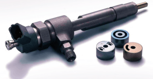
Somaloy Technology is the Soft Magnetic Composite (SMC) concept brand from Höganäs. The key concept is to produce components with 3D magnetic properties by pressing Somaloy powder to desired shape. Somaloy materials are composed of surface-insulated iron powder particles, which in one single step can be compacted to form components with complex shapes and tight tolerances.
Component manufacturing is based on the globally established, low cost powder metallurgy (PM) method. It is the 3D magnetic properties and the net shaping capabilities of Somaloy materials that open up new opportunities to design compact, light and cost-efficient solutions. Cost reduction can be obtained by reducing the total raw material cost as well as more efficient manufacturing and assembly. Somaloy technology meets future demands on efficiency, cost, performance and recyclability – in short a technology for the future!
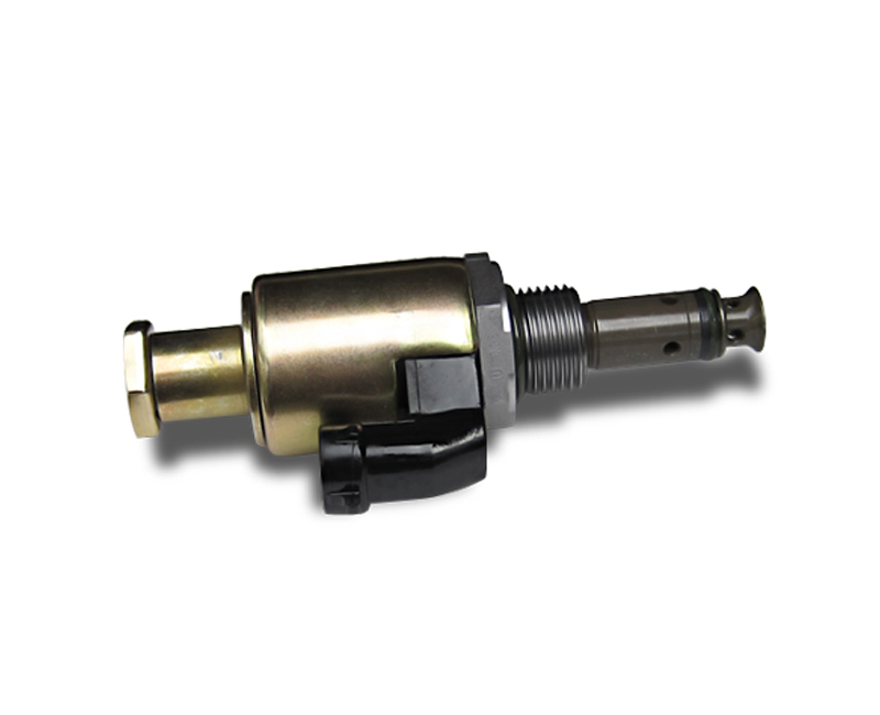
3126B Heui fuel pump available – not genuine
Adrenaline Cost*:
Pump $889.00 (caterpillar pn 1629610; part of: 1807341 or 10R2995)
Valve $234.00 (caterpillar pn 1225053)
Suitable for Delphi HTF100 Fuel Injector Pump Pressure Relief Valve
Suitable for Delphi IPR100 Bostech Fuel Injector Pump Pressure Relief Valve
*US marketprice.
*****
The use of non-genuine parts is not recommended by the brand.
On-line individual fuel injector diagnostics from instantaneous engine speed measurements
TECHNICAL FIELD OF THE INVENTION
[0001] The present invention generally relates to engine control systems and, more particularly, to a method and apparatus for diagnosing dead fuel injectors and correcting unbalanced fuel injectors.
BACKGROUND OF THE INVENTION
[0002] In a multi-cylinder reciprocating internal combustion engine, there are differences in the amount of useful torque produced by each cylinder, even during normal operation. Small between-cylinder torque differences can cause rough idling and poor emissions performance. Large between-cylinder differences can cause extremely rough operation and may indicate faulty cylinder and/or fuel injection components. The process of sensing these torque differences and using the information for compensation or diagnosis of engine operation is known as cylinder balancing.
[0003] Most present day electronically controlled engines include some form of interrupt-based engine speed sensing mechanism, which allows measurement of engine speed at very short intervals. Although there have been prior art systems which try to diagnose fuel injector malfunction off-line or when the engine is not running, they have generally proven to be unsatisfactory. There is therefore a need for a method and apparatus for diagnosing and correcting malfunctioning fuel injectors and unbalanced cylinders while the engine is on-line or running. The present invention is directed toward meeting this need.
SUMMARY OF THE INVENTION
[0004] Manufacturing/design imperfections and component failures in the fuel system/engine can lead to non-uniform torque production among the engine cylinders. Non-uniform cylinder torques can be observed as small engine speed fluctuations about the average engine speed at any given operating point. Engine speed data contains such fluctuations at different frequencies. The amplitude of these speed fluctuations at some known frequencies tell about the health of the fuel injectors and the engine. In the present invention, the instantaneous engine speed data is filtered by discrete band-pass filters to produce the engine speed fluctuations at particular frequencies. The output of the filters is identical to the power spectral density of the speed signal at those frequencies. The amplitude of each filter output is then compared to a user-defined threshold value. An amplitude larger than this threshold indicates the existence of low-fueling or high-fueling fuel injectors. If the amplitude is bigger than a second higher threshold, then this indicates the existence of dead fuel injectors.
[0005] In one form of the invention, a method for diagnosing malfunctioning fuel injectors is disclosed, comprising the steps of: a) sensing a speed of the engine a plurality of times during a time period; b) filtering the sensed engine speed, thereby producing engine speed fluctuation data at predetermined frequencies corresponding to specific fuel injectors; c) generating a fault code for fuel injectors with engine speed fluctuations exceeding a predetermined threshold.
[0006] In another form of the invention, a method for diagnosing malfunctioning fuel injectors is disclosed, comprising the steps of: a) sensing a speed of the engine a plurality of times during a time period; b) filtering the sensed engine speed, thereby producing engine speed fluctuation data at predetermined frequencies corresponding to specific fuel injectors; c) performing a program correcting the fuel injectors with engine speed fluctuations exceeding a predetermined threshold.
[0007] In another form of the invention, a method for engine cylinder balancing and diagnosing dead fuel injectors is disclosed, comprising the steps of: a) sensing a speed of the engine a plurality of times during a time period; b) filtering the sensed engine speed, thereby producing engine speed fluctuation data at predetermined frequencies corresponding to a specific fuel injector; c) comparing the filtered engine speed fluctuations to a first predetermined threshold value; d) comparing the engine speed fluctuations to a second predetermined threshold value when the engine speed fluctuations did not satisfy the threshold conditions in step (c); e) if the engine speed fluctuations did not satisfy the threshold conditions in step (d); performing steps (e.1) through (e.4); e.1) resetting all fuel injector trims to a predetermined value and calculating the total engine speed fluctuation; e.2) for a first one of the plurality of fuel injectors reducing fuel injector fueling by a predetermined value and calculating a new total engine speed fluctuation; e.3) generating a fault code for the first fuel injector when the calculated engine speed fluctuations from steps (e.1) and (e.2) are equal; e.4) repeating steps (e.1) through (e.3) for each remaining fuel injector; (f) if the engine speed fluctuations satisfy the threshold conditions in step (d); performing steps (f.1) through (f.3); f.1) adjusting the trim for the first fuel injector and calculating the total engine speed fluctuation; f.2) readjusting the trim for the first fuel injector until the calculated total engine speed fluctuation is at a local minimum; f.3) repeating steps (f.1) through (f.2) for all fuel injectors; g) generating fault codes corresponding to adjustments made to each of the fuel injectors.
BRIEF DESCRIPTION OF THE DRAWINGS
[0008] FIG. 1 is a schematic diagram of a prior art engine speed sensor.
[0009] FIG. 2 is a schematic block diagram of a first embodiment filter system of the present invention.
[0010] FIG. 3 is a graph of the frequency response of a discrete second-order band-pass filter used to calculate the spectral energy at half of the firing frequency.
[0011] FIG. 4 is a graph of engine speed variation (in revolutions per minute) versus frequency for a theoretical healthy engine.
[0012] FIG. 5 is a graph of engine speed variation (in revolutions per minute) versus frequency for a real-life healthy engine.
[0013] FIG. 6 is a graph of engine speed variation (in revolutions per minute) versus frequency for an engine with uneven fuel injectors.
[0014] FIG. 7 is a graph of engine speed variation (in revolutions per minute) versus frequency for an engine with one or more dead fuel injectors.
[0015] FIG. 8 is a schematic block diagram of a fuel injector diagnostics routine of the present invention.
[0016] FIG. 9 is a schematic block diagram of a cylinder balancing routine of the present invention.
[0017] FIG. 10 is a schematic block diagram of a dead fuel injector identification routine of the present invention.
DETAILED DESCRIPTION OF THE PREFERRED EMBODIMENT
[0018] For the purposes of promoting an understanding of the principles of the invention, reference will now be made to the embodiment illustrated in the drawings and specific language will be used to describe the same. It will nevertheless be understood that no limitation of the scope of the invention is thereby intended, and alterations and modifications in the illustrated device, and further applications of the principles of the invention as illustrated therein being contemplated as would normally occur to one skilled in the art to which the invention relates.
[0019] The present invention utilizes the detection of non-uniform cylinder torques as small observed engine speed fluctuations about the average engine speed for any given operating point of the engine. Therefore, the method and apparatus of the present invention utilizes the sensing of engine speed by any convenient means. FIG. 1 illustrates a typical prior art engine speed sensor, indicated generally at 10. Ferrous targets 12 are placed at fixed angular positions upon a rotating shaft 14, such as a crankshaft or camshaft, which rotates at a fixed relative speed to the engine speed. An appropriate sensor 16, such as a Hall effect sensor is placed so as to sense the passing of each of the targets 12 and to generate an output signal in the response thereto. This output signal is generally applied as an interrupt to a microprocessor such that the microprocessor can measure the time delay between successive outputs from the sensor 16 (and therefore also successive passings of the target 12). Those having ordinary skill in the art will recognize that the engine speed sensor 10 is illustrated by way of example only, and that there may be many different known methods for measuring engine speed.
[0020] In the preferred embodiment of the present invention, the output of the sensor 16 of FIG. 1 is coupled to an interrupt input port of an engine control module (ECM) microprocessor (not shown). It will be appreciated by those having ordinary skill in the art that nearly all modem engines incorporate a microprocessor-based ECM in order to manage various engine functions. It is intended that the process of the present invention be implemented as software code stored in a memory associated with such ECM microprocessor, the software code being executed by the microprocessor as described herein.
[0021] As shown in FIG. 2, the engine speed data collected by the ECM is filtered to determine the speed fluctuations at selected frequencies. In the preferred embodiment discrete second-order band-pass filters are used. It will be appreciated by those having ordinary skill in the art that other variations of band-pass filters could also be used such as third-order band-pass filters. Below is an example of the discrete second-order band-pass filter used in the preferred embodiment. 1H(z)=cos(Ψ)z2-γcos(ω T-Ψ)zz2-2γcos(ω T)z+γ2embedded image
[0022] where, Ψ and γ are filter design parameters, ω is the frequency of interest (rad/sec), and T is the sampling period (sec). The output of the filters is identical to the power spectral density of the speed signal at the filtered frequencies.
[0023] In the preferred embodiment there is one filter for each cylinder of the engine. Each filter corresponds to a fuel injector for a particular cylinder. For example, a six cylinder engine will usually have six filters although more filters could be used. For a six cylinder engine, the filtered frequencies will be ⅙, {fraction (2/6)}, {fraction (3/6)}, {fraction (4/6)}, ⅚, and {fraction (6/6)} times the firing frequency. The frequency filtered at ⅙ times the firing frequency corresponds to the fuel injector of the cylinder that fires first in the firing sequence of the engine. In the preferred embodiment a six cylinder engine is used. An example of the output of the filter of FIG. 2 having a filtered frequency of ½ the firing frequency is shown in FIG. 3. It will be appreciated by those having ordinary skill in the art that an engine having any number of cylinders could be used. For example, an eight cylinder engine would filter frequencies ⅛, {fraction (2/8)}, ⅜, {fraction (4/8)}, ⅝, {fraction (6/8)}, ⅞, and {fraction (8/8)} times the firing frequency and a four cylinder engine would filter frequencies ¼, {fraction (2/4)}, ¾, and {fraction (4/4)} times the firing frequency.
[0024] FIG. 4 illustrates a graph of engine speed variation (in revolutions per minute) versus firing frequency that can be generated using the filtered engine speed. The graph shown in FIG. 4 illustrates the filtered engine speed fluctuations of a theoretical perfectly healthy engine. There is no variation in engine speed because each fuel injector is providing exactly the same amount of fuel. The only engine speed variation occurs at the firing frequency. This is the peak which occurs at “ff”. This is due to the inevitable discrete nature of the combustion process.
[0025] FIG. 5 illustrates a graph of engine speed variation (in revolutions per minute) versus firing frequency for a normal healthy engine. Due to manufacturing tolerances, in real life, the fuel injectors will usually not be identical to each other. Therefore, each fuel injector may deliver a slightly different amount of fuel during an injector event. A cylinder having excess fuel injected into it will have a greater power contribution than a cylinder having less fuel delivered to it. A cylinder having too little fuel injected into it will not deliver as much power as cylinders with the appropriate amount of fuel injected. This over and under fueling causes speed variations in the engine. As can be seen on the graph, the speed variation at the six filtered frequencies differs slightly, but not significantly.
[0026] FIG. 6 illustrates a graph of engine speed variation (in revolutions per minute) versus the frequency for an engine with unbalanced cylinders. A predetermined amount of engine speed variation may be designated on the graph by the “Low threshold” line, corresponding to a maximum amount of tolerable engine speed variation. The graph indicates that the speed variation for cylinders 1, 2 and 4 exceed the predetermined lower threshold. This indicates that the fuel injectors for these cylinders are supplying either an excessive or an inadequate amount of fuel to their respective cylinders. When one of the cylinder speed variations is above the predetermined low threshold, the ECM will run a fuel injector balancing program, as discussed herein below.
[0027] FIG. 7 illustrates a graph of engine speed variation (in revolutions per minute) versus firing frequency for an engine with one or more dead fuel injectors. This graph is similar to the graph shown in FIG. 6, but the predetermined threshold is higher in FIG. 7. The second threshold can be set to a value that will indicate the presence for a dead fuel injector. If a speed variation of a cylinder is above the high threshold, a dead fuel injector exists. Fuel injectors 2 and 5 on the graph of FIG. 7 have speed variations which exceed the high threshold value. These fuel injectors are malfunctioning and should be repaired. If a speed variation of a cylinder is above the high threshold, the ECM will run a program which will determine which fuel injector is defective, as discussed in greater detail herein below.
[0028] FIG. 8 is a flow chart of the fuel injector diagnostics program. The sensed instantaneous engine speed is input to the filters at steps 801(a-e) to determine the engine speed variation at the designated frequencies. The filtered engine speed data is combined at step 802 which produces the total engine speed fluctuation. The engine speed variations are compared to a lower level threshold at step 803. If no speed variation is greater than the lower threshold, the process proceeds to step 804 which indicates that all fuel injectors are performing correctly and the engine is healthy. If any of the speed variations are determined at step 803 to be greater than the lower threshold, the ECM then compares the speed variations to a predetermined higher level threshold at step 805. If there is no speed variation above the higher level threshold, at step 806 the ECM runs a fuel injector balancing program. If any of the speed variations are above the high level threshold, the ECM runs a dead fuel injector identification routine at step 807.
[0029] FIG. 9 illustrates a flowchart of the cylinder balancing program discussed above. At step 901a, the program increases or decreases the trim of a first fuel injector and calculates the total speed fluctuation caused by the trim adjustment. The program then determines if the speed fluctuation is a local minimum at step 901b. If the speed fluctuation is at a local minimum at step 901b, the program begins adjusting the trim of the next fuel injector at step 902a until the new total speed fluctuation is at a local minimum at step 902b. If the speed fluctuation at step 901b is not at a local minimum the program readjusts the trim at step 901a. The process of adjusting the trim (steps 903a, 904a, 905a, and 906a) until the new total speed fluctuation is at a local minimum (steps 903b, 904b, 905b, and 906b) is repeated for each fuel injector. After the trim for each fuel injector has been calculated the ECM generates a fault code corresponding to the adjustments made to the fuel injectors at step 910.
[0030] FIG. 10 illustrates the dead fuel injector identification routine discussed above. The program is preferably only used if the speed variation at a cylinder is above the higher level threshold. The program begins at step 1001 by resetting all fuel injector trims to one and calculating the total speed fluctuation this action causes. The program then reduces the first fuel injector fueling by a predetermined amount and calculates a new total speed fluctuation at step 1002. In the preferred embodiment the fuel injector fueling is reduced by 25%. At step 1003 the computer compares the speed fluctuation caused by resetting the fuel injector trims to one to the speed fluctuation caused by reducing the first fuel injector fueling by 25%. If the speed fluctuations are equal, this indicates the fuel injector is dead and a fault code is generated at step 1005. If the speed variations are not equal the fuel injector is healthy and the program proceeds to step 1004. This routine is repeated for each fuel injector.
[0031] Those having skill in the art will therefore appreciate that, in the present invention, the instantaneous engine speed data is filtered to produce the engine speed fluctuations at particular frequencies. The amplitude of each filter output is compared to a predetermined threshold value. An amplitude larger than this threshold indicates the existence of low-fueling or high-fueling fuel injectors. If the amplitude is bigger than a second higher threshold, then this indicates the existence of dead fuel injectors. The present invention therefore diagnoses dead injectors and balances misfiring cylinders while the engine is on-line or running, representing a significant improvement over prior art off-line systems.
[0032] While the invention has been illustrated and described in detail in the drawings and foregoing description, the same is to be considered as illustrative and not restrictive in character, it being understood that only the preferred embodiment has been shown and described and that all changes and modifications that come within the spirit of the invention are desired to be protected. For example, while the present invention has been described hereinabove with respect to a six cylinder engine, those having ordinary skill in the art will recognize that the processes described hereinabove are equally applicable to engines having fewer or greater numbers of cylinders.
Berco Product finder & cross ref.

Caterpillar ® Haul Road Design and Management
In both surface and underground mining, poorly designed and maintained haul roads can lead to dramatically increased costs